While building the "place order" feature, developers often end up mixing screen flow and internal object calls in a single diagram.
Planners, on the other hand, want to know "what the system does when the customer enters something."
The tool that answers these two questions separately is the
system sequence diagram
(SSD).
A UML sequence diagram shows the calls that objects make to one another. An SSD shows only the exchanges between an actor outside the system and the system as a whole.
Here the system is a black box.
The diagram does not show which objects are inside or which methods are called.
That makes it useful in the requirements analysis stage for checking the scope of a feature and its inputs and outputs.
Read the main flow of the use case one step at a time, and look for the requests the actor makes to the system.
Suppose the main flow of the "place order" use case is as follows.
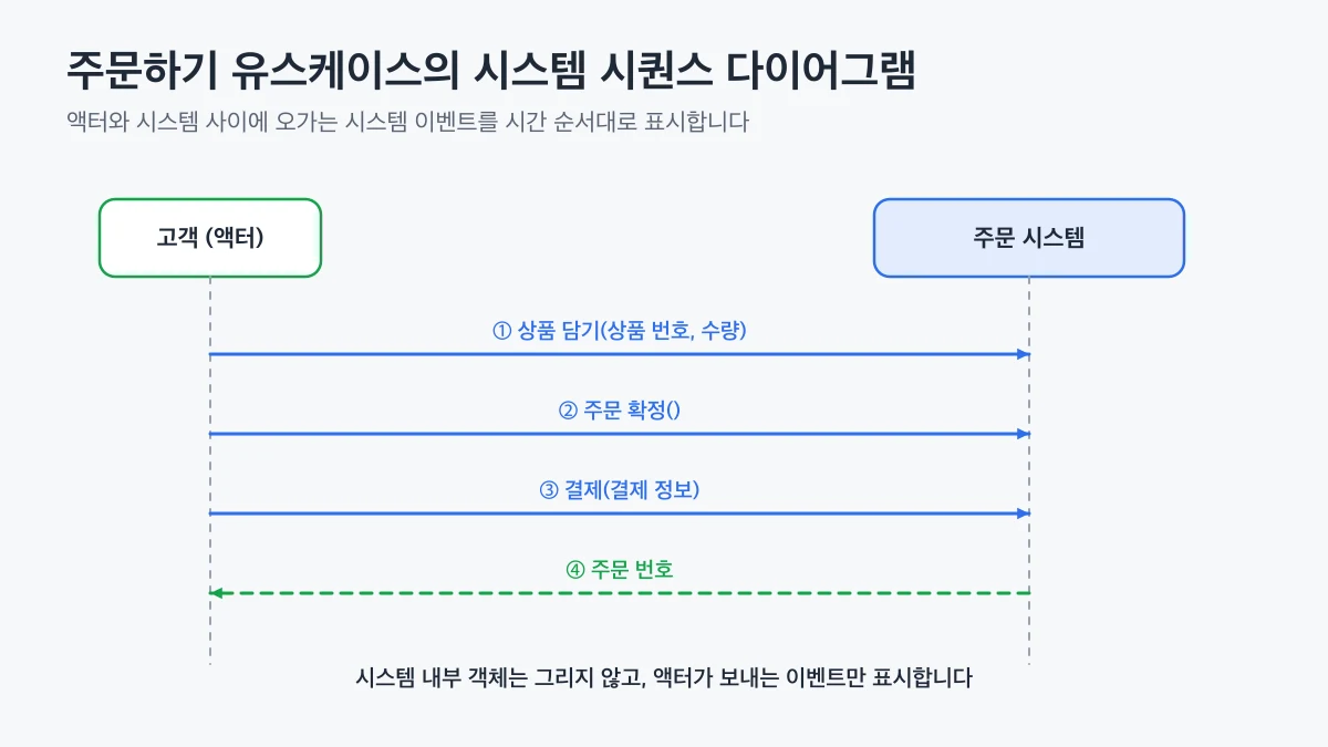
The customer enters a product number and a quantity to put the product in the cart.
The customer confirms the order.
The customer enters payment information.
The system shows the order number.
Steps 1 through 3 are events that the customer sends to the system, and step 4 is the response that the system returns.
Name each event so that it expresses the user's intention.
A customer actor sends add-to-cart, confirm-order, and payment events to the system box, and the system returns the order number in a system sequence diagram
The SSD and the UML sequence diagram both draw the order of messages, so they look alike.
But they depict different things.
Aspect
System sequence diagram
UML sequence diagram
What it depicts
The actor and the system as a whole
The objects inside the system
Nature of the messages
Events the user sends to the system
Method calls between objects
Main stage of use
Requirements analysis
Design
What it verifies
Scope and inputs and outputs of the feature
How the objects collaborate
If you do not keep this distinction, internal calls such as "call the payment approval API" or "save the order" easily creep into the SSD.
Then the scope of the feature becomes unclear, and design decisions get mixed into the requirements document.
👍
If you put internal calls into an SSD, the requirements review fills up with technical terms that the planner cannot judge.
Always write events
Check a finished SSD against the following criteria.
Is each event written as an action of an actor outside the system?
Has the same feature been given different event names in several use cases?
Do the parameters of each event contain only the information that is needed?
For example, the parameters of "add to cart" need the product number and the quantity, but not the price or the stock level of the product.
The system has to decide the price and the stock, so it is natural to leave them out of the event.
👨💻
If the same event appears in several use cases, unify its name from the start.
If the event name keeps changing, the same feature tends to be implemented twice in later stages.
A system sequence diagram is a tool that shows only the
system events
that an actor sends to the system.
Find the events in the main flow of a use case and draw them separately from internal calls, and you can confirm the scope of the feature in a diagram that planners can also read.
 System Sequence Diagram - System Events from Actor Input